 Figure 3
Set A, the frame, cylinders and running gear Regner order nbr. 20100
 Figure 3
Only small problems have been encountered when assembling this building block, the instructions are clear and easy to follow.

The bearings of the axes are in fact square-shaped slabs with a hole drilled through the centreline to act as sleeve bearing. At the underside a threaded hole is made, although with very limited windings. When this hole is left open, the oil for lubricating the shafts will be lost; I block these holes by putting a little grease in them. See figure 3. The purists in live steam will connect piping to the threaded holes to create some kind of central lubricating system to lube the three driving shafts.
 Figure 5
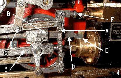
The combination lever does hit (see arrow A in figure 4) the crossheads (see arrow B in figure 4), but Henk Bunte of "Modelbouwatelier Apeldoorn" had advised me to twist the connecting rod (see arrow C in figure 4) so combination lever will pass the crosshead. Needless to say that this twisting of the connection rods should not result in extra friction with the slide bars rod (see arrow D in figure 4), with this the problem was remedied. Also was it necessary to mount the slide bars a little higher on the cylinder glandhouse in order to place this parallel with the cylinder rods. A washer rod (see arrow E in figure 4) is used for shimming. This was also seen by someone else’s Regner model, he also had to add a shim to complete his 99.4701.
The screw marked with arrow G in figure 4 had to be shortened by one mm at the threaded end. This to avoid collision with the crosshead when running forwards at maximum slide valve stroke (limited expansion).
The quartering of the wheels is done by adjusting the first and third axis with the coupling rods in place. When these rotate without binding the second axis can be placed. This second axis floats in its vertical position freely, and therefore disturbs proper quartering.
Strange the couple rod is not split, when rolling over small rail nflatness the second axis cannot follow this. The wheel suspension can absorb smooth track unflatness with ease, the third shaft is fixed in the frame while de first shaft is suspended by springs, free to translate or tilted, the second shaft is free floating and does not carry the engine. A better solution would be to divide the coupling rods, or a vertical slotted hole in the coupling rod as LGB does. This slotted hole is added in a later stage. See figure 5. The second shaft can be lifted for 1 mm without disturbing the free running of the other shafts.

A lot of time was consumed to let the expansion die-block slide smoothly through the expansion link. These expansion links make a small angle with the radius rod to the slide valve therefore the force needed the move the expansion die-block is quite high. According to the building instruction the return cranks must be positioned in such manner that one of the edges (see arrow A in figure 6) comes in line with the wheel hub (see arrow B in figure 6). This results in a (to) large stroke for the slide valve. After completing the engine I measured the actual stroke of the slide valve and reduced the stroke accordingly. According to the building instruction the stroke of the slide valve should measure 5mm, I have the return crank adjusted that the stroke of the slide valve becomes 5-6 mm.
Also the cosmetic parts such as the brakes, pilot and buffer beam can be assembled. The standard servo simple fits on supports already present on the frame. It is wise to mount the servo at this stage because later it is inaccessible. As rod, I used parts from the junk box. This rod between the servo and valve gear is rigid and an in length adjustable solid bar, this in contrast to what Regner instructions suggests in the building description.